Purpose: Used to define rightmost boundary of lanes in general geometry Girder System Projects. (Not applicable to Line Girder Projects.)
--> Given in girder system input
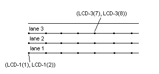
Lists of coordinates (feet or meters) defining the shape of the lane boundary on the right side of each lane, looking from the beginning to the end of the bridge. LCD-1 is the right boundary of the rightmost lane and defines the right curb line. (Only two points would be required for a straight line). It is imperative that the end points of a lane boundary be placed well outside the abutments. If any girder in the system does not extend from abutment to abutment, lanes (LCD-i) cannot be used and wheel distribution must be supplied for live loading. (See WDD-i , WDF-i , WDR-i , WDS-i )
A polynomial curve is fit to the set of points if no more than twelve points are given for a lane boundary. Linear interpolation is used if more than twelve points are given. The boundary on the left side of each lane is defined using LANWID. The first value in each pair is the "x" coordinate, the second value is the "y" coordinate. For example, 40 values would be given in the list if 20 points were used to define the shape of a lane boundary.
Note: If the condition FLOAT LANES is used, the rightmost lane boundary must be aligned with the right curb line.
Lane Layout/Lateral Distribution in General Girder System Projects
Loading Definition Input Reference