Purpose: Used to define girder coordinates in general geometry Girder System Projects. (Not applicable to Line Girder Projects.)
--> Given in girder system input
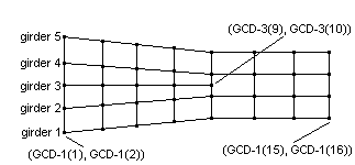
Lists of global coordinate pairs (right handed coordinate system required) giving the location of nodes (feet or m) in girder "i" where bracing intersects the girder or supports are located (see SUP-i). The first value in each pair is the "x" coordinate and the second value is the "y" coordinate. For example, 24 values would be given for girder "i" if that girder has 12 bracing incidences. Girder 1 and the highest numbered girder must be fascia.
Note that girders must be numbered in order proceeding from the right exterior girder toward the left exterior girder. The plot typically is rotated so that girder 1 is aligned with the bottom edge of the plot boundary. GCD-i then must be given proceeding from left to right along the girders after the plot is rotated. The end nodes on a girder should be placed at the bearings, i.e. short girder overhangs at the abutments should not be included in the model. (If these girder overhangs are defined with GDREXT data then the weight of these overhangs will be included girder output reaction tables.)
Curvature is not calculated from given coordinates, so user must supply radius at all tenth points of all girders if there is curvature (see RAD-i).